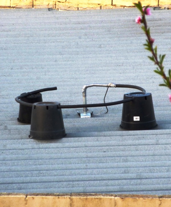
The story of the DDRR makes interesting reading,
and I have always had a yearning to build one of these unusual antenna’s except there are better directional alternatives.


 After moving house a few years ago from the top of one of the highest locations close to the centre of the city of Melbourne where a simple quarter wave 9′ stainless whip performed well, I had the instruction from my wife NO ANTENNAS on the new house!
Well that was never going to be good so I had to come up with a very low profile CB antenna that worked well enough to be able to talk some DX when the bands opened and at least get back to Melbourne stations over 50 miles away.
Luckily our new location is on the tip of a peninsula surrounded by Bay water on one side and ocean on the other.
Well the 9′ stainless managed to hide itself on the back corner of the house unobtrusive when you drive towards our house overlooking the bay. After using it for a while I had the thought maybe the DDRR could add some needed gain towards Melbourne in the North across the bay.
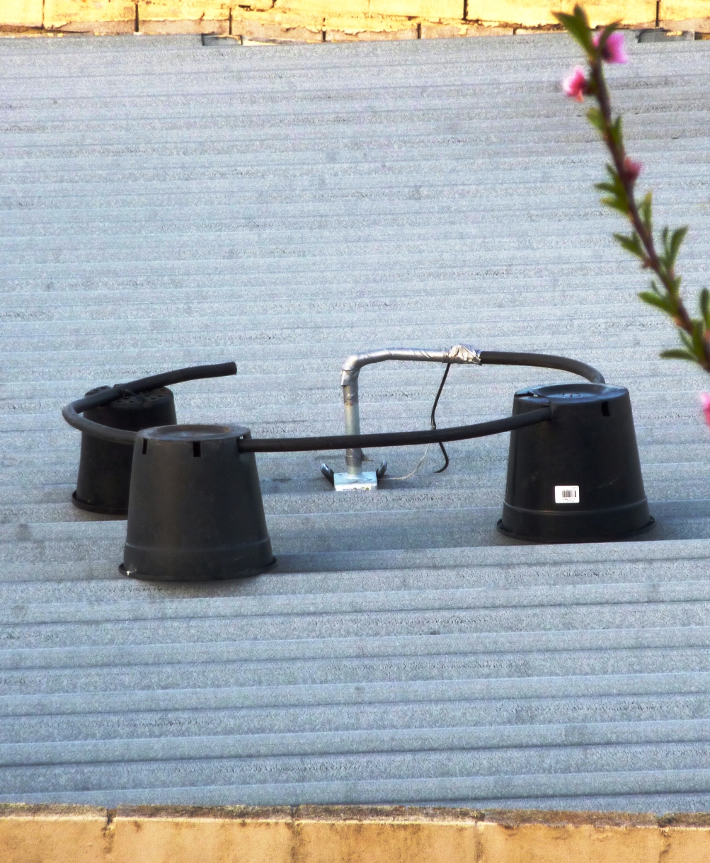
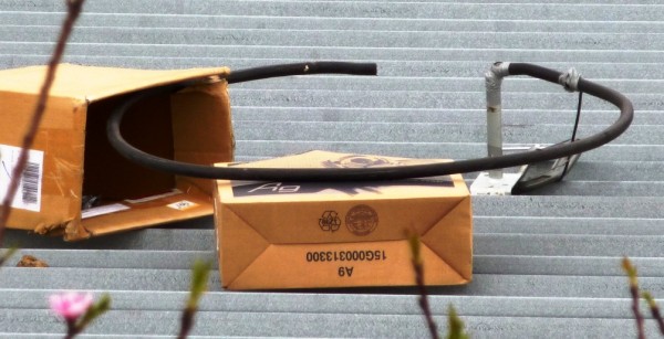
As the DDRR only sits 12″ above the flat iron roof of the two storey house we have, it is invisible but effective in giving some usable forward gain in the co-phased 90 degree out of Phase configuration I am driving it in with the 9′ stainless.

Obviously the direction will be fixed in place and the antenna gain direction immovable.
As I want all my signal to go to the US – North East from Australia and across Port Phillip Bay from my Bellarine Peninsula location- no problem![]()
The 9′ stainless mobile base is mounted on an alloy mag wheel clamped direct to the roof is 3′ in from the edge for minimum ground plane and radiation to the South West.
I also have the DDRR antenna which is effectively another 9′ verticle, positioned about 18′ to the NE on the roof also.
The trick to make it a director to the NE is to feed the 2 antenna verticle array C0-Phased and “90 degrees OUT of PHASE”
So the Co-Phasing Harness needs to be constructed from a SO239 Splitter with one side a 9′ length of SEVENTY FIVE OHM (TV High Quality) Coax to a PL259 to plug into the leading or Director antenna in this case the DDRR. The DDRR has the center of the coax feed going to the earthed ring radiator about 8″ from the verticle riser from the roof where it is supported.
The coax earth/braid goes to the base of the antenna connection to the roof which seems to be the point where the SWR is best. This is not according to the directions in antenna books and articles but it works! The biggest advantage of this DDRR antenna is the fact that it puts the whole co-phased system at earth potential which kills the static that usually plagues verticle antennas! BUT DOES NOT kill the RF from my 64″ LG Plasma TV which peaks on ch#35!! (The Australian Defacto Call CH#) Any other CH# is OK!
The other side needs to be a 18′ length of 75 Ohm TV Coax to a PL259 to plug into the following or 9′ Stainless Verticle Reflector antenna.
This will create a directional array with reasonable gain. I DONT want to put a figure on it, because I dont make antennas for a business and need to lie about the real gain.
But I have proved the configuration does provide about 1-2 S Points over the 9′ alone in the chosen direction to the North East.
This configuration is reasonably stealth because its the only “visual pollution” my wife will tolerate!
She can see the 9′ stainless sticking up but cant see the DDRR as it is only 12″ high off the surface of the middle of the roof.
The plan is to make 4 DDRR’s and position them like a beam to the NE across the roof as I have the space and they need the perfect ground.
Should make 8-10DBi I guesstimate.
Setting up and testing the DDRR was pretty easy! Its amazing how well a lump of copper cable can work like this!

