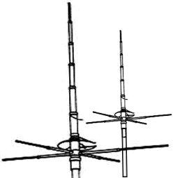
Using CB Vertical antenna’s co-phased for forward directional extra gain.
Co-Phasing can be used if you have Two vertical antennas and some room.
PRO’s
- Forward Directional Gain
- Low Cost
- Can be different types
- Simple Construction
- Low SWR
- Vertical Polarisation
CON’s
- Fixed Direction
- Mounting and Spacing
- Vertical Polarisation
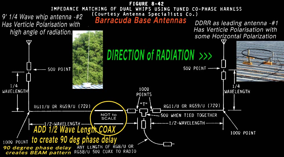
The solution to obtaining good forward gain from 2 verticals is to feed the 2 antenna array “90 degrees OUT of PHASE”
This concept transforms the normal 360 degree verticaly polarised radiation from one vertical antenna and takes the bi-directional concentrated radiation of adding another close by, forcing both antennas into a forward projecting beamwidth.
This “Out of Phase” configuration forces the two antenna’s normal bidirectional operation into each acting differently, similar to a two element verticaly polarised beam.
One Vertical Element acting as a Director and the other acting as a Reflector depending on the Phasing Harness connection.
This is despite the fact that both are “Driven” vertical elements as both are connected as normal to the coax phasing harness ends.
The actual direction is determined by the length of the co-phase harness side connected to each antenna.
To create the “90 deg.out of Phase” condition the coax “T” splitter has two different lengths of 75 Ohm TV High Quality coax terminated in a PL259.
One coax length is a Quarter Wave (at center operating frequency)
and the other coax side is a Half Wave long terminated in a PL259.
So the Phasing Harness needs to be constructed from a SO239 Splitter with one side a 9′ length of SEVENTY FIVE (75) OHM (TV High Quality) Coax to a PL259 to plug into the leading or Director antenna.
The other side needs to be a 18′ length of 75 Ohm TV Coax to a PL259 to plug into the following or Reflector antenna.
This will create a directional vertically polarised array with reasonable gain if positioned 1/2 Wave length apart.
Its not a technical evaluation, but I have proved the dual 90 degree Out of Phase antenna configuration does provide about 1-2 S Points over the one vertical antenna alone in the chosen direction.
I have also tried this with a 9′ Stainless Vertical and a DDRR. (Direct Driven Ring Radiator HERE)
The DDRR has the inherent advantages of small size and earthed radiator giving low static floor as well as slight vertical directivity.
This original content by AX05 is Copyright CQDX11.net 2012


Hi Greg,
I don’t do anything with 11m stuff. Happened across this article because a friend had seen it and showed it to me, wondering if he could build a simple “beam” for his 11m radio. So thought I’d point out a critical error here.
If you want to drive cross-fire arrays at 90° phase shift you need 1/4 wavelength spacing between the driven elements, not 1/2 wave. At 1/2 wave spacing and 90° phase shift, the signal will arrive at the feedpoint of the array at 270 degrees out of phase, ending up with an array that is symmetric end-fire. To steer a half-wave spaced array out to end-fire in one direction, you need a 180 phase shift:
phase shift = k*d sin(theta) = pi*sin(90) = pi = 180°
Spacings at odd 1/4 wavelength multiples are asymmetric end-fire with 90 degree phase shift in the direction of the element with leading phase angle. Spaced at even 1/4 wave multiples, they are symmetric end-fire.
Hi Chris, just spotted this comment VSS, thanks for the information on the directional characteristics of phase shift. I must have got it wrong somehow so will definitely look into your explanation further. To clarify my current harness arrangement needs the front DDRR to be moved back a qtr wave closer to the rear 9’whip? This would be great as I would like to try a parasitic DDRR in front of the driven DDRR to see if I can get more gain to the USA.
I will do this very soon and report back here on the results, cheers, 73’s – GREG PS Have updated the information above to link to my other website (href=”http://cqdx11.com/cb-radio-antennas-at-barracuda-base/” target=”_blank”) where there is more info.