- This topic has 0 replies, 1 voice, and was last updated 12 years, 2 months ago by
Greg 43AX005.
-
AuthorPosts
-
2013/12/20 at 1:06 PM #1049
Greg 43AX005
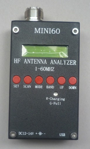
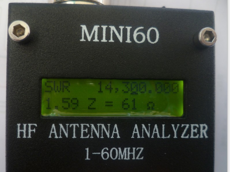
MemberHave one of these purchased off ebay and it has been indispensable in working out resonant frequencies of many antenna systems so far. Seems very accurate in measurement of impedance of feed-lines and antennas.

Was pleasantly surprised to find my co-phased DDRR and 9 foot whip were measuring the lowest at 27.365 on 48 Ohms with a SWR of 1.8:1
Even tested a lot of 50 Ohm bnc coax terminators and most were on 50/52 Ohms but one was 63 Ohms so guess it works.

FEATURES
Hardware:
Precise and self-calibrating reflectometer design measures forward and reflected signals and impedance data
Display 2×16 with optional backlight
Precision DDS signal generator (AD9851) used as signal source
USB port connects to PC for field-upgradeable software and uploading of real-time measurement data
Buzzer
Operation:
Manual control option displays SWR and complex impedance at selected frequencies
Automatic scanning results displayed as frequencies of lowest SWR and complex impedance
Battery operated for field use or use external 13.8V wall adaptor
Power saving modes
Multi-point calibration for better accuracy
Instrument Capabilities:
Measure antenna electrical parameters: SWR, impedance (resistance + reactance), capacitance, inductance
Measure feedpoint impedance
Measure ground loss
Adjust antenna tuners and determine loss
Measure inductors and capacitors
Measure coax transmission line (SWR, length, velocity factor, approximate Q and loss, resonant frequency, and impedance)
Measure and determine optimum settings for tuning stubs: SWR, approximate Q, resonant frequency, bandwidth, impedance
Determine characteristic impedance of transmission line
Determine length of ¼ and ½ wave phasing lines
Coaxial Cable Loss
Determine antenna tuner loss
Measure balun loss
Measure inductor Q
Estimate quartz crystal parameters
Measure magnetic loop resonance and SWR
SPECIFICATIONS
Frequency Generation & Control:
1 – 60 Mhz
Source impedance: 50 Ohms
Stability: +/- 100 ppm
Spectral Purity: Harmonics down >- TBD dB beyond 60 MHz
Step Size: User configurable increments of 100 Hz, 1 kHz, 10 kHz, and 100 kHz
Usable Measurement Range:
SWR: 1.0 to 9.99
Impedance: approx. 5 to 2000 ohms
RF Output:
Adjustable: 2.0 Volts pp (typ)
Power supply:
3.7v li-on battery
External: 12 to 14 Volts DC, 500mA
Controls:Pushbuttons (5): “Mode”, “Band”, “Config”, “Scan”, “Up”, “Down”
Switch: “Power On”
Connectors:
RF Out: BNC
USB: Mini-B receptacle
External power: 2.1mm Power Jack (center pin positive) -
AuthorPosts
- You must be logged in to reply to this topic.